

Ground fault protection is a critical aspect of electrical power system design, especially in medium-voltage networks like 4.16 kV systems. Recently, concerns have arisen regarding the adequacy of neutral grounding resistor (NGR) ratings and the sensitivity of protective relays in detecting low-level ground faults. This blog post delves into these issues, highlighting key considerations and providing recommendations to ensure robust and compliant ground fault protection.
The Technical Dilemma
In reviewing the system specifications and protection schemes, a discrepancy has been identified between the prescribed NGR ratings and industry standards:
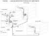
- AMIES-P-100, Clause 7.3.3.2 specifies a 50 A NGR for the 4.16 kV system.
- AMIES-P-111, Clause 5.1 mandates that the grounding system be designed per IEEE 142, which recommends NGR ratings between 100 A and 1000 A for low-resistance grounding, typically around 400 A.
Further complicating matters, the protective relays employed (SEL-451) have minimum pickup settings that may not detect ground fault currents below certain thresholds due to the current transformer (CT) ratios in use.
Key Issues Identified
Inadequate NGR Rating:
- The 50 A NGR may not comply with IEEE 142 recommendations.
- The NGR must be appropriately rated to handle the system's total charging current, generally 2–5 times this value, to ensure effective fault detection and safe operation.
Relay Sensitivity and CT Ratios:
- CT Ratio Concerns: The existing CTs have ratios of 4000:5 A and 1250:5 A. With a minimum relay pickup of 0.25 A secondary, the minimum detectable ground fault currents are 200 A and 62.5 A primary, respectively.
- Protection Gap: Ground faults below these thresholds may go undetected, posing safety risks and potential equipment damage.
Incomplete Charging Current Study:
- The charging current calculation only considered cables at 2201-SG-3-1, estimating approximately 10 A.
- A comprehensive study should include all capacitive components, such as additional cables, transformers, and connected equipment, with the total charging current being three times the single-phase value.
Protection Relay Coordination:
- Reliance on upstream 13.8 kV feeder relays for ground fault protection at the 4.16 kV incomer is ineffective due to the delta-wye transformer configuration, which blocks zero-sequence currents.
- The 4.16 kV incomer relays must be capable of detecting and isolating ground faults independently.
Recommendations for Effective Ground Fault Protection
Reassess NGR Rating:
- Compliance with IEEE Standards: Increase the NGR rating to align with IEEE 142 guidelines, considering a value between 100 A and 1000 A, typically around 400 A.
- System Charging Current: Ensure the NGR rating is at least 2–5 times the total system charging current to facilitate fault detection and limit transient overvoltages.
Optimize CT Ratios and Relay Settings:
- Adjust CT Ratios: Implement CTs with lower ratios (e.g., 1000:5 A) to enhance sensitivity, reducing the minimum detectable ground fault current.
- Sensitive Relay Functions: Utilize relay functions capable of detecting low-level ground faults, such as zero-sequence or residual ground fault protection with lower pickup settings.
Incorporate Core-Balance CTs:
- Enhanced Detection: Install core-balance (zero-sequence) CTs that encircle all three-phase conductors, enabling detection of ground faults with currents as low as a few amperes.
- Relay Compatibility: Ensure protective relays are compatible with core-balance CT inputs and can be configured with appropriate sensitivity settings.
Conduct a Comprehensive System Study:
- Accurate Charging Current Calculation: Perform a detailed analysis that includes all capacitive elements within the system to determine the accurate total charging current.
- Ground Fault Analysis: Evaluate potential ground fault scenarios and their impact on system protection and coordination.
Review Protection Scheme Coordination:
- Selective Coordination: Establish a hierarchy of protective devices that ensures faults are isolated at the closest point, minimizing system disruption.
- Protection Zones: Define clear protection zones within the system to improve fault isolation and enhance safety.
Collaborate with Contractors and Consultants:
- Design Verification: Engage with contractors to review and verify the protection scheme design, ensuring all calculations and settings are justified and documented.
- Third-Party Assessment: Consider consulting independent experts to audit the protection scheme for compliance with industry standards and best practices.
Conclusion
The effectiveness of ground fault protection in medium-voltage systems hinges on the appropriate selection of NGR ratings and the sensitivity of protective relays. The identified issues underscore the need for a thorough review and adjustment of the existing protection scheme. By increasing the NGR rating, optimizing CT ratios, and employing sensitive detection methods, the system can achieve robust ground fault protection that complies with IEEE standards.
Implementing these recommendations will not only enhance safety but also ensure the reliability and longevity of the electrical infrastructure. Open communication and collaboration among all stakeholders—engineers, contractors, and consultants—are vital to address these challenges and achieve a compliant, effective ground fault protection system.
References
- IEEE Std 142-2007, "IEEE Recommended Practice for Grounding of Industrial and Commercial Power Systems"
- SEL-451 Protection Relay Technical Manual
- AMIES-P-100 and AMIES-P-111 Project Specifications

![Schneider Electric's [Circuit Breakers] : Latest Products](https://lh3.googleusercontent.com/blogger_img_proxy/AEn0k_tHP2YTOekxiRZ5vNL_n3JqAqN_IdzM0_BzHx42Kyx0KxU4fXHKARmWmEoBQ8AA27ZIGn-c2mI2afCLnxUDGtblg8TRMoMqiq0PWt8INpm9Dl1i92uYbRbpP0uNj8iMbEnswlTK8_m5g6c5pe0EbyKCy_WT3yZ0OaFYYFCmpus=w100)
0 Comments